- Hardware:
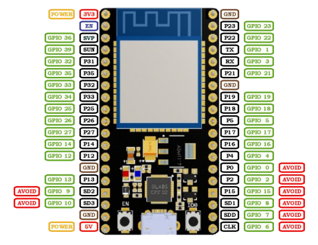
- NodeMCU ESP-32S – microcontrollers (2)
Pinout (home-made):
- AHT20 – sensor
- Can measure the temperature and the humidity
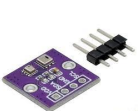
- BMP280 – sensor
- Can measure the temperature and the air pressure
-We use these two in a combined sensor:
-BMP280+AHT20:
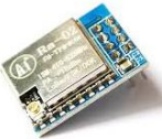
LoRa SX1278 – radio transmitter
A long range, low consumption, radio device.
2. Initial libraries and firmware:
First, we had to upload MicroPython to the ESP32s so that they can understand python.
For this we downloaded a library called esptool. (This can be done using the command prompt: pip install esptool)
Then we erase the flash by inputting “esptool erase_flash”, and we can install the MicroPython firmware. The file that we need can be found here on the official MicroPython website “https://micropython.org/download/ESP32_GENERIC/”.
Finally, we can upload it to the ESP32s using this command: “esptool –chip esp32 write_flash -z 0x1000 ”.
Then we get the mpremote library by using “pip install mpremote”. Then we test if the computer can detect the connected ESP32 with “mpremote repl”. After this we expect something like „Connected to MicroPython at COM”, if this is right, we can start programming
3.Testing the sensors and the LoRa:
Let’s start with the sensors. First, we must download the appropriate drivers, so the microcontrollers can read the sensor data. The AHT20 sensor has and official driver that can
be found on this link:
https://raw.githubusercontent.com/targetblank/micropython_ahtx0/master/ahtx0.py.
The BMP280 lacks an official driver, but David Stenwall has written a working driver that we can use:
https://github.com/dafvid/micropython-bmp280/blob/master/bmp280.py.
Now that we have the drivers, we can start writing the code that tests the sensors. This code looks something like this:
from machine import Pin, I2C
import ahtx0
import bmp280
import time
# Setting up I2C bus
i2c = I2C(0, scl=Pin(22), sda=Pin(21))
# Initializing sensors
aht = ahtx0.AHT20(i2c)
bmp = bmp280.BMP280(i2c, addr=0x77)
# Requesting and printing data
while True:
temp_aht = aht.temperature
hum = aht.relative_humidity
Written by: Regőczi Áron
2025.11.29-30
temp_bmp = bmp.temperature
pressure_hpa = bmp.pressure / 100
temp_diff = temp_aht - temp_bmp
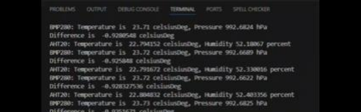
print("AHT20: Temperature is ", temp_aht, "celsiusDeg,
Humidity", hum, "percent")
print("BMP280: Temperature is ", temp_bmp, "celsiusDeg,
Pressure", pressure_hpa, "hPa")
print("Difference is ", temp_diff, "celsiusDeg")
# This is constantly ~-1C so the sensors are somewhat
offset from each other
time.sleep(1)Now we can connect the sensor and upload the code to the ESP32. The connections are
quite simple:
| Sensor Pin | ESPS32 Pin |
| VDD | 3V3 |
| GND | GND |
| SDA | P21 |
| SCL | P22 |
Now a little about the code handling of the ESP32. It’s important to note that a local file cannot be run on just a computer, it must be copied to the microcontroller along with the necessary drivers. Some useful command related to this: (very useful for testing)
| mpremote ls | lists the files on the ESP32 |
| – mpremote cp : | copy a file to the ESP32 |
| – mpremote rm | remove a file from the ESP32 |
| – mpremote run | run a file on the computer on the ESP32 |
So, we upload the two drivers and finally run the code.
The test is a success; the sensors are working.
Now its time for the LoRa. These aren’t extremely different from the sensors other than the code being more complicated. First, we upload the driver to the microcontrollers. The file is found here: https://github.com/sergio303/micropython-sx127x/blob/master/sx127x.py.
Then we upload it to the ESP32s using the aforementioned “mpremote cp ”.
Then we can make the connections and connect the antennas (which are ideally around 17-
18cm long). The 8 connections that we must make:
| Lora Pin | ESP 32 Pin |
| MISO | GPIO19 |
| DIO0 | GPIO26 |
| SCK | GPIO18 |
| MOSI | GPIO23 |
| RST | GPIO14 |
| NSS | GPIO5 |
| GND | GND |
| VCC | 3V3 |
If the connections have been completed, we can check if the LoRa is being detected by our machine. This snippet of code looks like this:
from machine import Pin, SPI
from sx127x import SX127x

spi = SPI(1, baudrate=1000000, sck=Pin(18), mosi=Pin(23),miso=Pin(19))
pins = {"ss": 5, "dio0": 26, "reset": 14}
lora = SX127x(spi, pins, {"frequency": 868e6})
print("SX version:", lora.readRegister(0x42))
This code prints the chip variant which is usually 18 (0x12). Any other value usually indicates wiring issues.
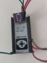
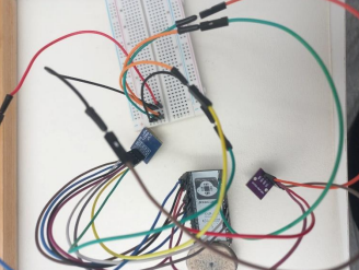
If this works, we can connect one of the ESP32s with a LoRa and the sensor. This is not difficult, since the only matching pins are the 3V3 and the GND pins. These have been connected using a breadboard.
Then we can write the semi-final code of the transmitter :
from machine import Pin, SPI, I2C
from time import sleep
from sx127x import SX127x
import ahtx0
import bmp280
# SPI setup
spi = SPI(1, baudrate=1000000, sck=Pin(18), mosi=Pin(23),
miso=Pin(19))
# LoRa pins
pins = {"ss": 5, "dio0": 26, "reset": 14}
# LoRa parameters
params = {"frequency": 868e6, "sync_word": 0x34}
# Initialize LoRa
lora = SX127x(spi, pins, params)
# Configure LoRa
lora.setFrequency(868e6)
lora.setTxPower(14)
lora.setSpreadingFactor(9)
lora.setSignalBandwidth(250000)
lora.setCodingRate(5)
lora.enableCRC(True) # Error detection
# I2C setup
i2c = I2C(0, scl=Pin(22), sda=Pin(21))
# Sensor setup
aht = ahtx0.AHT20(i2c)
bmp = bmp280.BMP280(i2c, addr=0x77)
# Send data
while True:
temp_aht = aht.temperature
hum = aht.relative_humidity
temp_bmp = bmp.temperature
pressure_hpa = bmp.pressure / 100
temp_diff = temp_aht - temp_bmp
msg = "Temp AHT20: {}, Humidity: {}, Temp BMP280: {},
Pressure: {}, Temp Difference: {}".format(temp_aht, hum,
temp_bmp, pressure_hpa, temp_diff)
lora.println(msg)
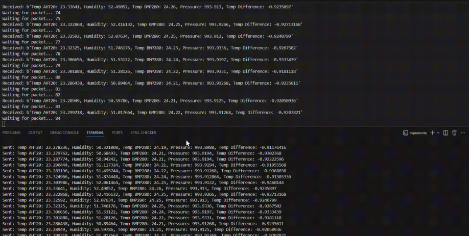
print("Sent:", msg)
sleepThis code initiates the LoRa module and configures it to be relatively fast with a long range and sends the sensor data as a string every second. The code also uses CRC to make sure that
the other ESP32 can detect when the received packet is corrupted.
After this we set up the receiver. We just upload the LoRa driver and make the connections with the LoRa. Now we can write the receiver code:
from machine import Pin, SPI
from time import sleep
from sx127x import SX127x
# SPI setup
spi = SPI(1, baudrate=1000000, sck=Pin(18), mosi=Pin(23),
miso=Pin(19))
# LoRa pins
pins = {"ss": 5, "dio0": 26, "reset": 14}
# LoRa parameters
params = {"frequency": 868e6, "sync_word": 0x34}
# Initialize LoRa
lora = SX127x(spi, pins, params)
RX_DONE_MASK = 0x40
# Configure LoRa
lora.setTxPower(14)
lora.setSpreadingFactor(9)
lora.setSignalBandwidth(250000)
lora.setCodingRate(5)
lora.enableCRC(True) #Error detection
# Put module in continuous receive mode
lora.receive()
counter = 0
# Wait for packets
while True:
 irq = lora.getIrqFlags()
if irq & RX_DONE_MASK:
 payload = lora.readPayload()
 print("Received:", payload)
 lora.receive()
 else:
 counter += 1
 print("Waiting for packet...", counter)
 sleep(1)
This code also initiates and calibrates the LoRa, then starts listening for incoming packets. We will be naming the main scripts as main.py (“ mpremote cp :main.py”), because the ESP32s automatically executes “main.py” on startup. Finally, we can do a final hardware test by naming the receiver and transmitter code main and uploading them to the ESP32s then giving them power. By using the terminal, we can see that the test was successful.
Written by: Áron Regőczi
Adapted for the website by: Boldizsár Fazekas
2025.11.29-30
